Fan Actuated Inverted Pendulum Control System
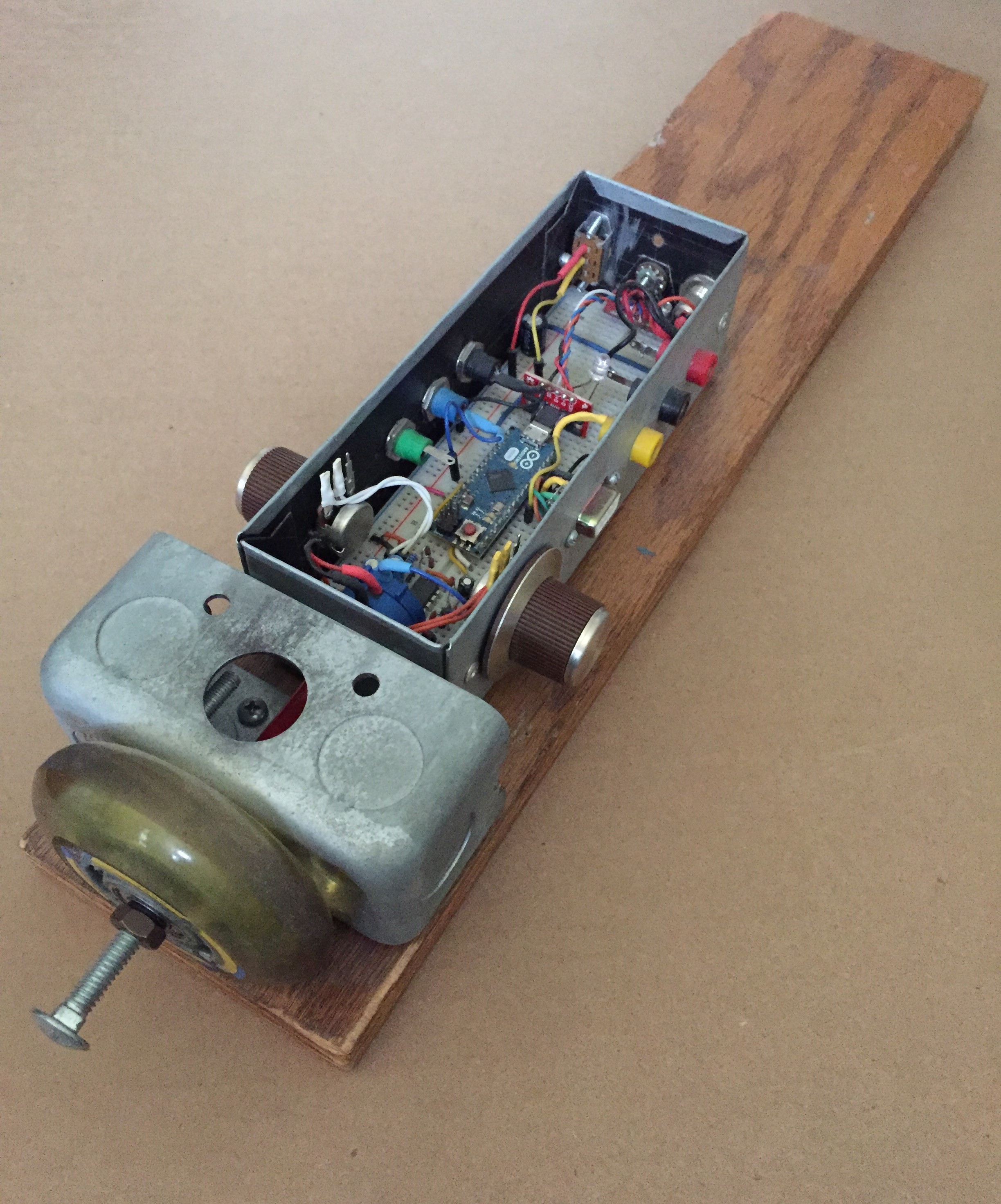
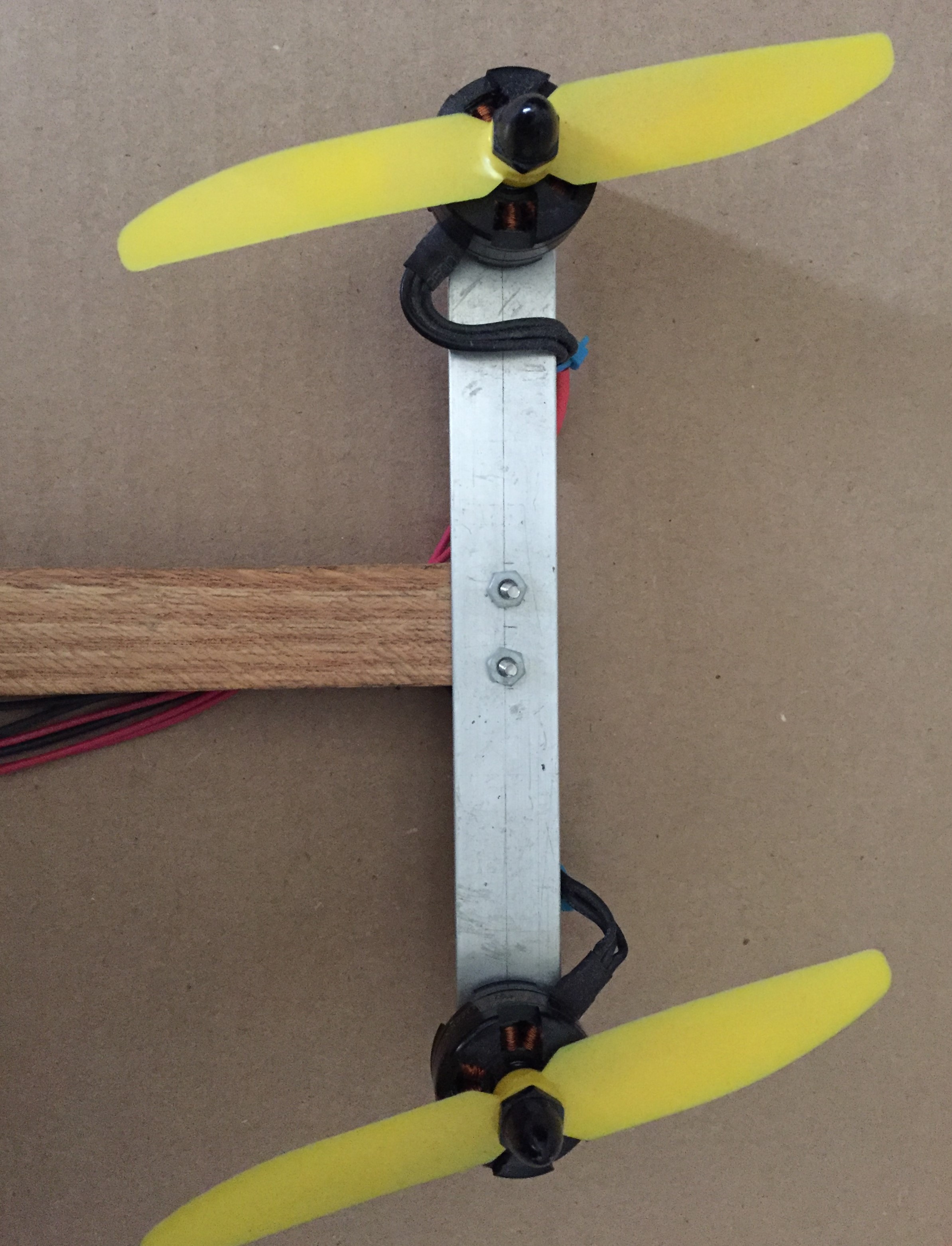
This was the final project that my buddy Chad and I turned in for a modern control systems design course (The only proof I have of his existence is a link to his LinkedIn. If he were available for hire I would recommend him to everyone -- he gave me a bunch of stuff so he's cool). The system is a modified inverted pendulum problem -- instead of the pendulum being mounted to a moving cart or a swinging arm, the pivot point is fixed, and a pair of fans are attached to the far end. The goal was to design an optimal LQR controller for the system to keep the pendulum in the upright position using the two fans, and to implement it digitally on an arduino.
Without going into too much detail, the process was essentially this: (0) build the system, (1) derive the equations of motion from a free body diagram, (2) assign the two inputs as non-conservative forces in the equations, (3) generate a linearized state space model of the system, (4) assess its stability as determined by the eigen values of the state matrix and also by extracting transfer functions from the time domain model, (5) Verify controllability and observability, (6) Design and build an electronic interface for measurement/state estimation as well as for actuation, (7) write a matlab script to solve the algebraic Spaghetti equation, (8) Simulate in Simulink, (9) Write the C code for state measurement and estimation, and for the controller gains as obtained from the solution to the algebraic Jumanji* equation, and (10), test it out.
(* Chad came up with this one)
Simplifications
Along the way, we tried to get away with as many simplifications as we could. Firstly, the dynamical model of the pendulum was linearized -- which was part of the assignment. Next, we assumed a linear thrust relationship for the fans, though it is well known that the relationship is a square function. And finally we excluded entirely the dynamical response of the motors and fans from the model of the system. Their only appearance in the Simulink model was as a pair of guestimated first order transfer functions external to the system state space model. In this way, we essentially introduced two system states which were not fed back (so technically, our controller was not LQR at all!). I ended up going back and deriving a more accurate model, as can be seen in this messy Mathematica notebook. The short story is that I found the motor/fan assembly to have a (slightly) underdamped 2nd order response when linearized -- so two of these as actuators makes the whole linearized system 6th order. Also funny is the fact that the 1st order transfer functions we introduced to simulate the fan dynamics have almost exactly the same rise time as the 2nd order systems derived from first principles.
Measurement and State Estimation
For mechanical simplicity, the only state directly measured was the angle of the pendulum. This was accomplished with a multiturn potentiometer mounted to the pivot point. You might laugh, but this is how we did it:
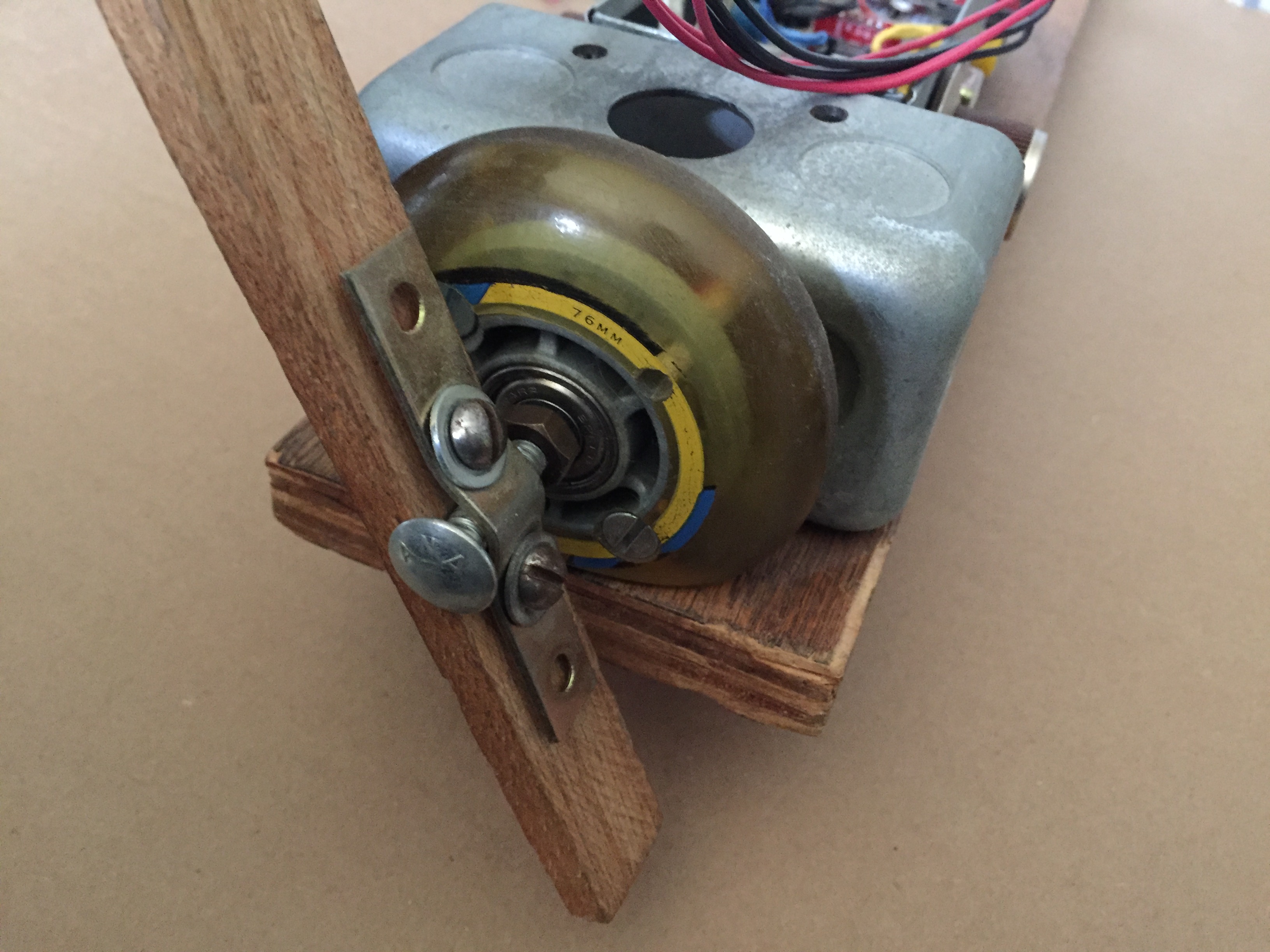
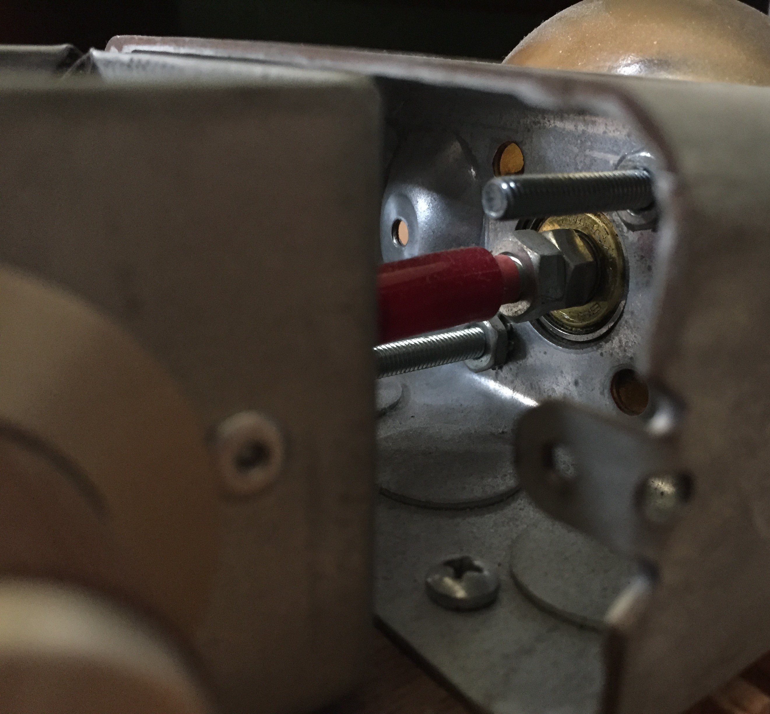
Behind this rollerblade wheel is a connection to the pot -- below you see the jam nuts and the rubber thing I used to make the connection:
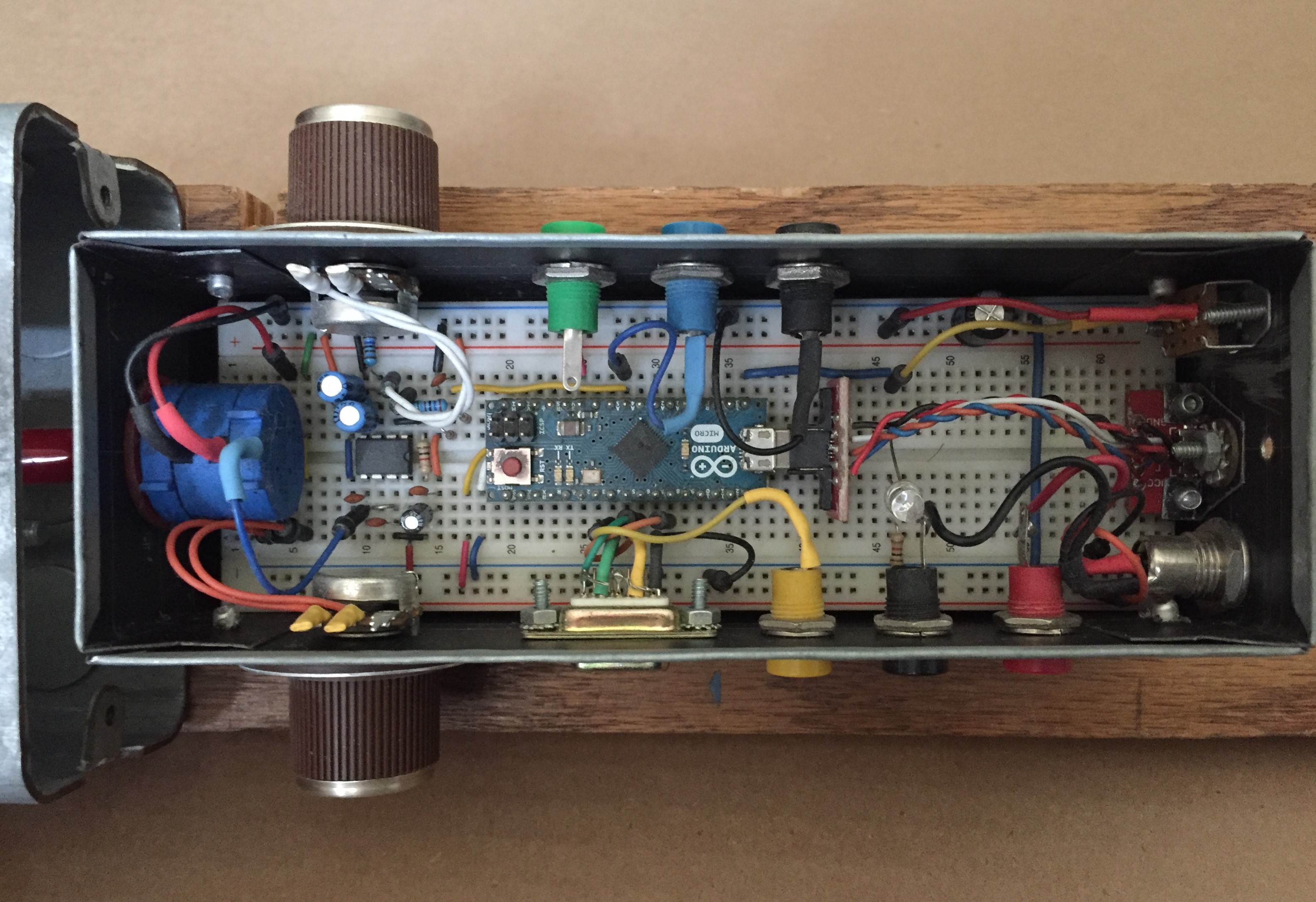
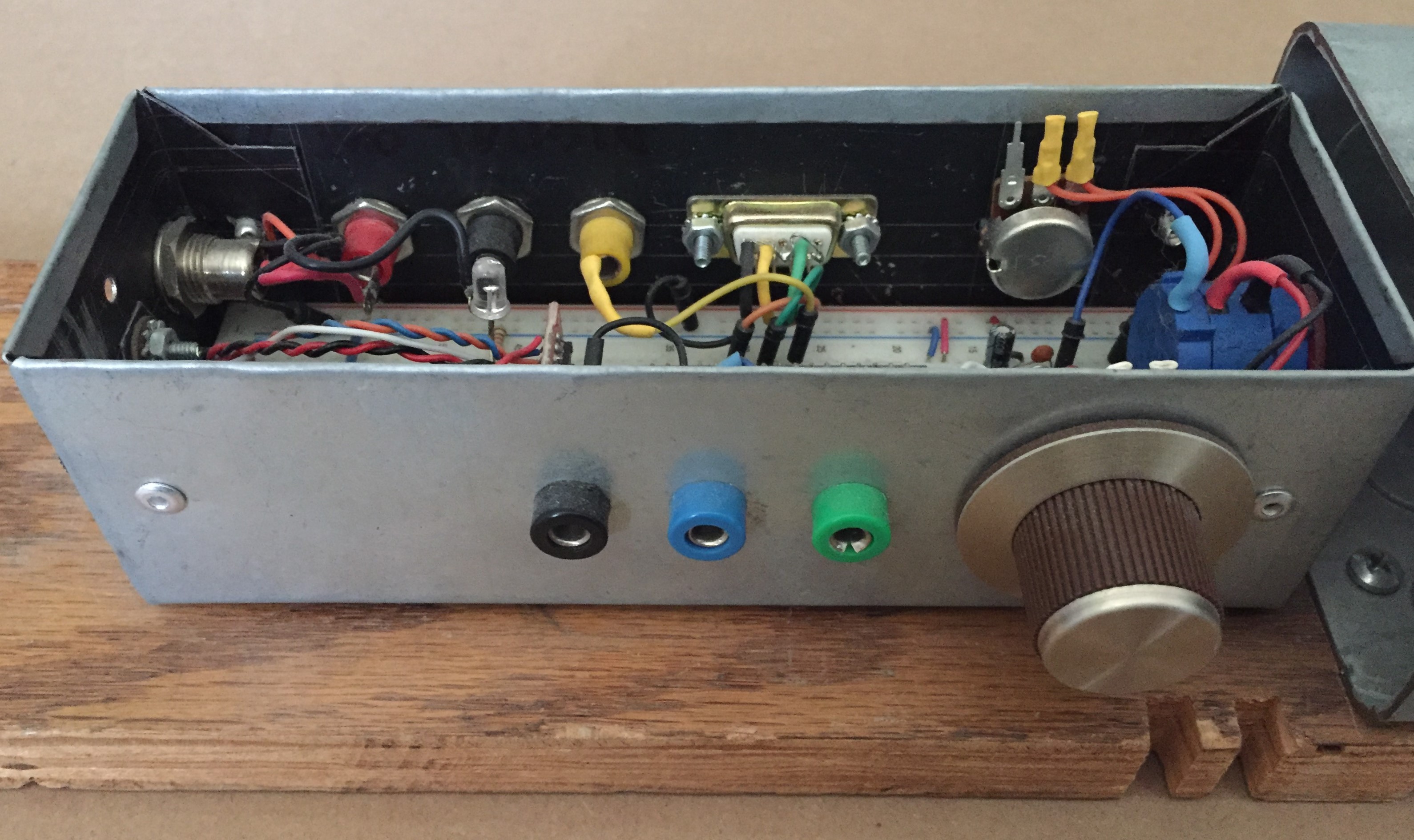
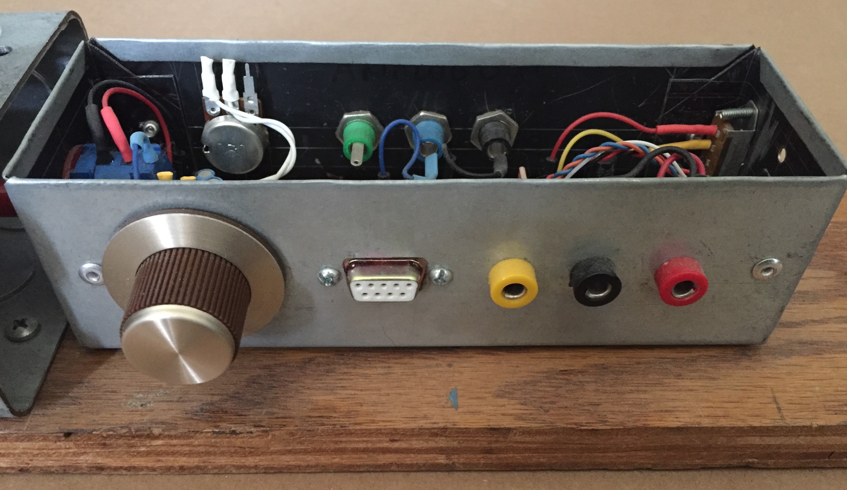
I wanted to have a little bit of freedom to manipulate the system electronically, so I added a variable gain amplifier and an adjustable reference so measurement gain and offset can be played with (pots shown in the picture). This measurement is read into an Arduino Micro, where the rest of the controller lives. The full circuit in its sheetmetal box is shown below:
The other state of interest in the simplified model was the angular speed. Calculating this is not as simple as applying the definition of the discrete derivative, since quantizing error, clock jitter and the measurement circuit itself introduce enough noise to make a derivative calcuated this way look like complete garbage. We ended up implementing a simple second order IIR filter in C to get a usable derivative signal with very good results.
Here are some more glamour shots of the sheetmetal box: The first one shows the connections for measurement used during setup, and the next one shows the power and control connections
Actuation
Engineers beware the "intuitive" throttle interfaced programming of commercial hobbyist BLDC controllers. These can really ruin your day. That's all I have to say about that.
First Tests
The controller itself was really no big deal to make -- these days, you can just have Matlab or Mathematica solve the algebraic spaghetti equation for you, and have an optimal controller ready to go -- you just have to play around with the cost function and figure out how to add and multiply numbers. Here is a little video from before I made the nicer packaging:
Also, check out that Mathematica link I put above -- I give a pretty detailed account of the propellor and motor system there.